Load-bearing slip ring
My mother is a pedicurist and from her pedicure practice, she has requested an engineering task. It involves a UV lamp that needs to hang from an articulating arm to be multipurpose, serving both hands and feet. In the past, I attempted to solve this without a slip ring, which turned out to be very dangerous as the wire was twisted and posed a fire hazard, depicted in Figure 1.
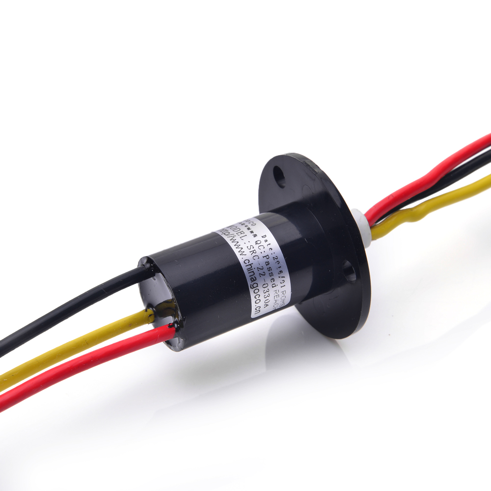
I began this project with the search for a slip ring. On Aliexpress, I found a slip ring with 3 channels capable of handling 10A for 15 euros Figure 2. In hindsight, this was considerable overkill, and the slip ring was quite large. Then I searched for a bearing to carry the weight of the UV lamp. These are available in large diameters but never come with mounting holes. Therefore, I started looking for 3D-printed bearings capable of axial loads. That’s when I found the bearing by thegoofy on Thingiverse, which is a slew bearing and a parametric design downloadable for Fusion 360. More detail in Step 2.
Now that my essential components were specified, I could begin the design process.
Step 1: Sketch slip ring in CAD
- To create a design, it is necessary to have a 3D sketch of the slip ring to use as a reference
Figure 3.
Step 2: Download slew bearing
- Download the slew bearing from thegoofy on
Thingiverse- Download the slew bearing with correct parameters from stocki_occ by thegoofy on
Thingiverse - Download the slew bearing with spacers from thegoofy on
Thingiverse
- Download the slew bearing with correct parameters from stocki_occ by thegoofy on

![]()
- Modify the parameters of the slew bearing to ensure that its holes align with those of the reference slip ring in the design workspace
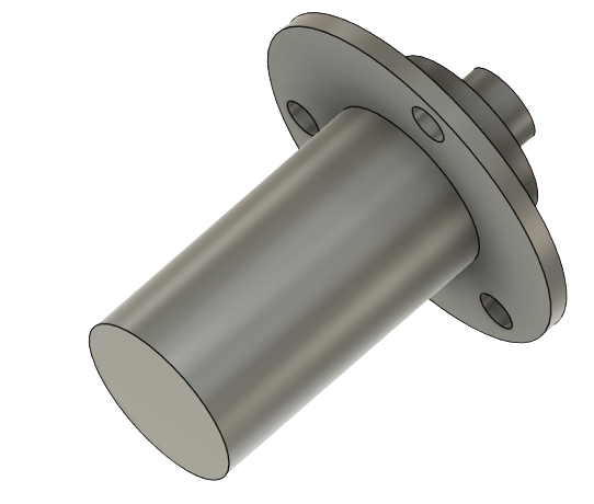
Step 3: Sketch mounting point of the articulating arm
- Sketch the mount point from the articulating arm to the slew bearing
Figure 6. This is done using a loft.
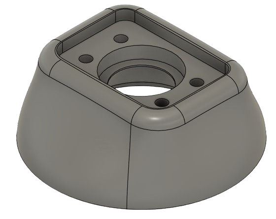
Step 4: Sketching the mounting point of the UV lamp
- Sketching the mount point from the UV lamp to the slew bearing
Figure 7.- Requiring disassembly of the UV lamp to neatly conceal the mounting, utilizing heat inserts
Figure 8&9.
- Requiring disassembly of the UV lamp to neatly conceal the mounting, utilizing heat inserts


Step 5: Soldering
-
Soldering the the wiring for the plug that goes into the UV lamp.
-
Soldering the wiring that goes thorugh the articulation arm.


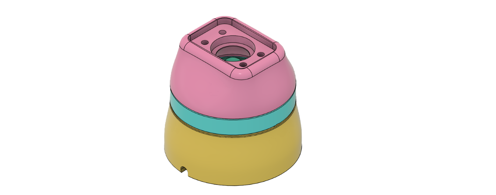
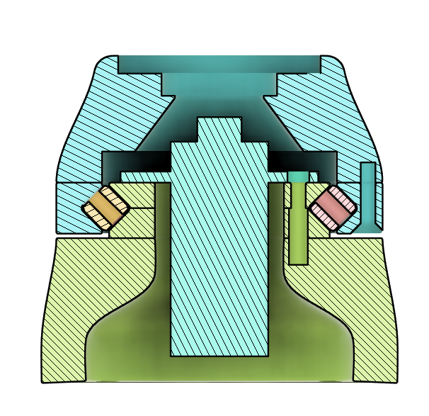
Result
The end result is visable in the section view and the video below.
Conclusion
With the excellent design by thegoofy, designing the Custom Load-Bearing slip ring was manageable. The result looks professional, and compared to the previous solution, there can be no user error by turning the UV lamp in the same direction too often.
Recommendations
For next time, I would consider a different slip ring for several reasons: This slip ring was rather large, it was overkill and quite expensive. Also, the top could be merged with the outside of the slew bearing. This simplifies the design by saving three screws and three heat inserts.