Tool holder v2
Introduction
After completing a successful internship at Waag Futurelab in Amsterdam, I was hired as a freelancer to further develop a tool holder they were working on. My focus was on optimizing its functionality and design. The project, which lasted about a week, was driven by an upcoming Open Day where the updated tool holder was needed. During this time, I applied my technical expertise and deepened my skills in designing a product specifically for 3D production and easy open-source fabrication.
I will link their devolopment here: …
Criteria
The ultimate goal is to create an interactive, universal tool holder that seamlessly integrates composite motions with user input and allowing for easy tool interchangeability.
Here’s an improved version of your design criteria points for better clarity and flow:
Design Criteria:
-
Develop in Fusion 360:
The tool holder must be designed using Fusion 360 to ensure Waag Futurelab can easily access and modify the design after my involvement. -
Adaptable, Self-Centering Mechanism:
The design must accommodate tools of varying diameters (with a max of 32mm) and lengths, allowing them to be installed and automatically centered within the holder. -
Composite Motion:
The holder should support two types of motion—swinging/rotating along the y-axis and revolving around the z-axis. -
Design Constraints:
- The attachment point must align with two predefined screw holes.
- Two servo motors need to be embedded to control motion in both axes (y and z).
- The overall size must fit within the constraints of the AxiDraw plotter.
- The tool holder must be durable enough to withstand upward pressure during operation.
Previos development
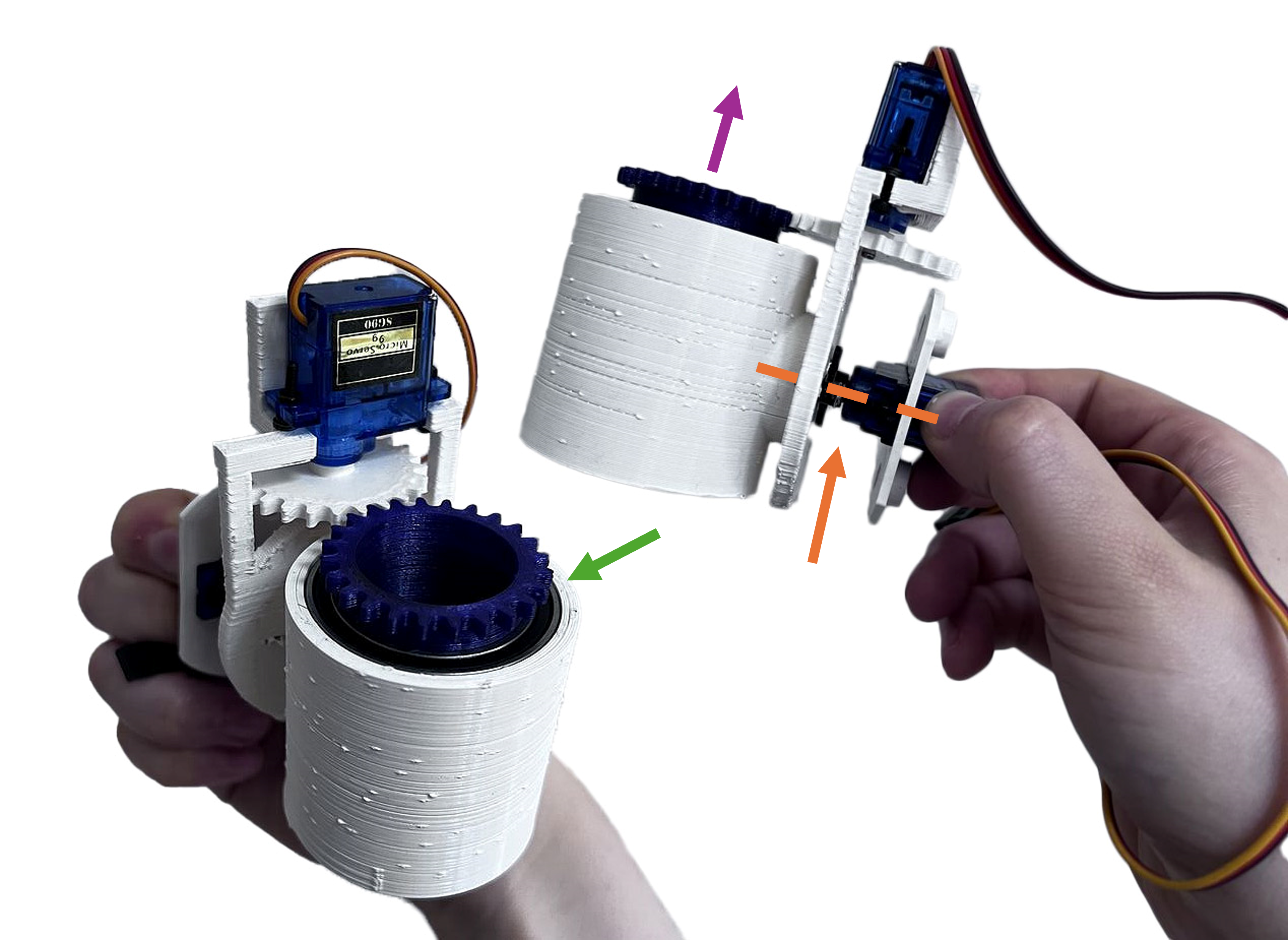
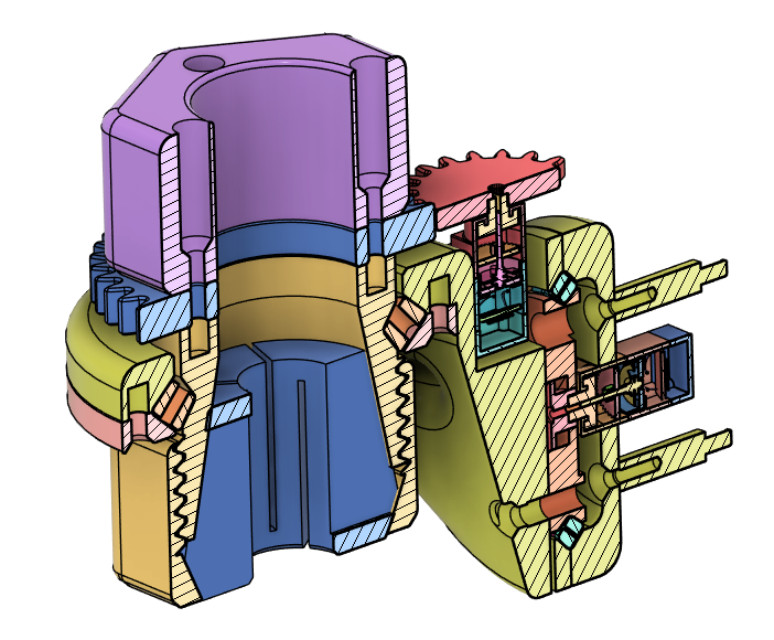
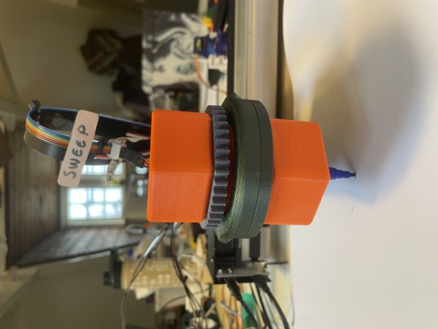
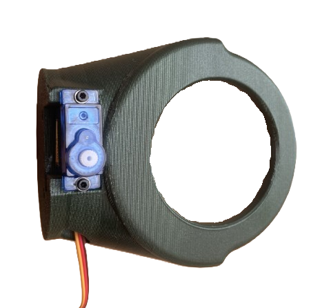
Several iterations have been made, with the final iteration visible in Figure 1. This iteration closely followed the design criteria.
Issues Encountered
-
Sturdiness:
The design lacks sturdiness, as indicated by the orange arrow inFigure 1. All weight and pressure from the tool are concentrated on the servo motor axis, leading to stability issues. -
Revolving Cylinder:
The revolving cylinder was not properly mounted. Under upward pressure, shown with the purple arrow inFigure 1, it tends to pop out of place. -
Bearings:
The use of store-bought bearings is a limiting factor due to their expense and limited size options, as shown with the green arrow inFigure 1. -
Self-Centering Mechanism:
The centering is achieved by clamping with sponges, but this method lacks precision, as demonstrated inVideo 1.
Potential
Despite these issues, the design shows promise. The technical concept appears to work, as demonstrated in Figure 1. Further development and refinement are needed, preferably with the assistance of someone skilled in technical drawing.
Research
After identifying the issues in the previous iterations, I immediately recalled a past project I worked on called “Load-bearing Slip Ring”. You can read more about this project here. A 3D-printed bearing, like the one from stocki_occ by thegoofy on Thingiverse, can address three of the four major problems:
- Load-bearing: It can handle the load on the orange axis.
- Mounting Points: Custom bearings can be designed with mounting points for the revolving part.
- Customizable Dimensions: With 3D printing, bearings of any dimension can be created.


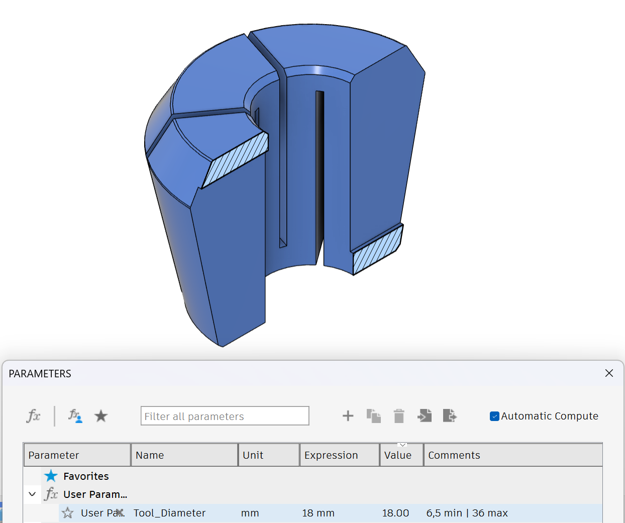
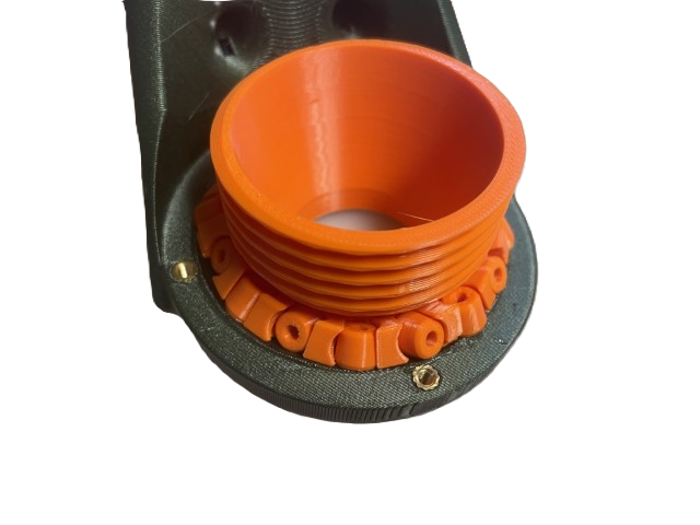
For the fourth issue (self-centering mechanism), I conducted secondary research and found a 3D-printable collet clamping system from dodasch on Printables. By printing collets of various diameters, a wide range of tools can be accommodated.
Updated Design
With a comprehensive understanding of the project, I envisioned a clear path for improvement. Building on the solid foundation laid by previous iterations, the first iteration of the updated design worked from the start and encoutered only a small hikup with the bearing, which made the overall development process smooth and efficient.
The issue I encountered involved a 3D-printed bearing with spacers that were too large, preventing the bearing from rotating. This was resolved by removing the spacers. While troubleshooting, I discovered a better 3D-printed bearing, which I will discuss further in the recommendations.
To use the collet system mentioned in the Research I had to backward engingeer the .stl file. Also the design was to small for the tool diamter critiria i had. So i changed the file so by changing 1 perimiter tool sizes from 6,5mm to 36mm could be accomdinated Figure 4.
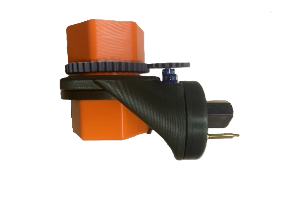
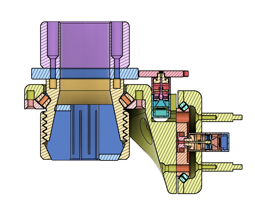
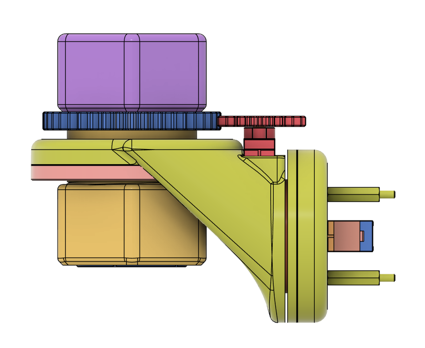
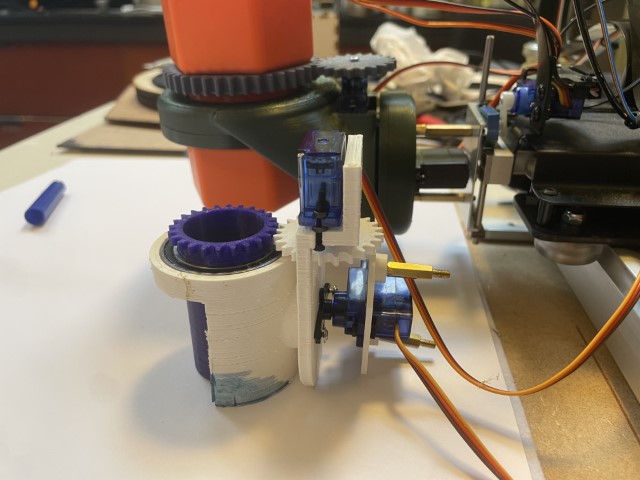
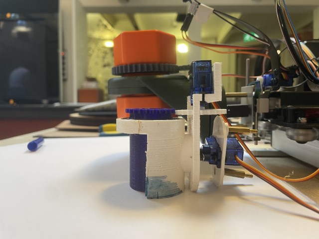
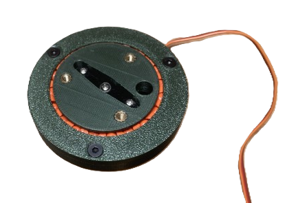
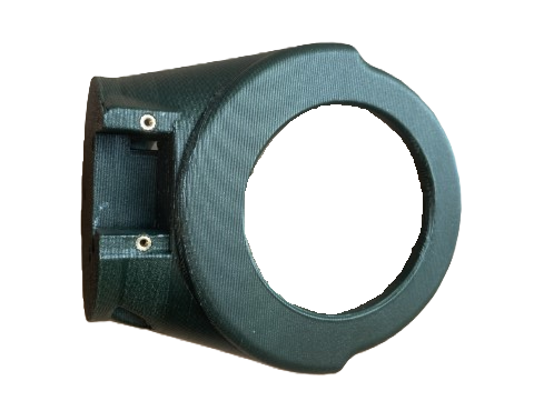
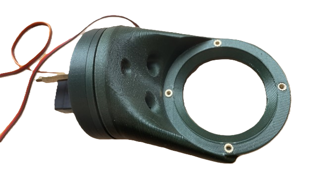
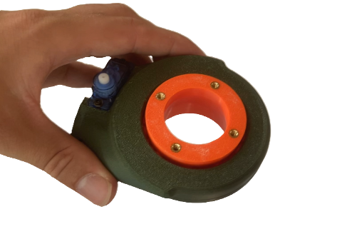
Final result
I’m really happy with how this design turned out, especially considering the time I had. During testing, it met all the criteria and was ready for the Open Day—referred to as the Open Waag by the Waag. I was also invited to observe how people interacted with Tool Holder v2. Initially, it worked as expected, but as people began customizing tools and adding more load to the servos, the 180-degree servo gearbox broke. I didn’t anticipate this issue, but I will propose a solution in the recommendations .
Below are some pictures of the final design, alongside a comparison with the previous iteration, as well as a video showcasing all the composite motions.

Recommendations
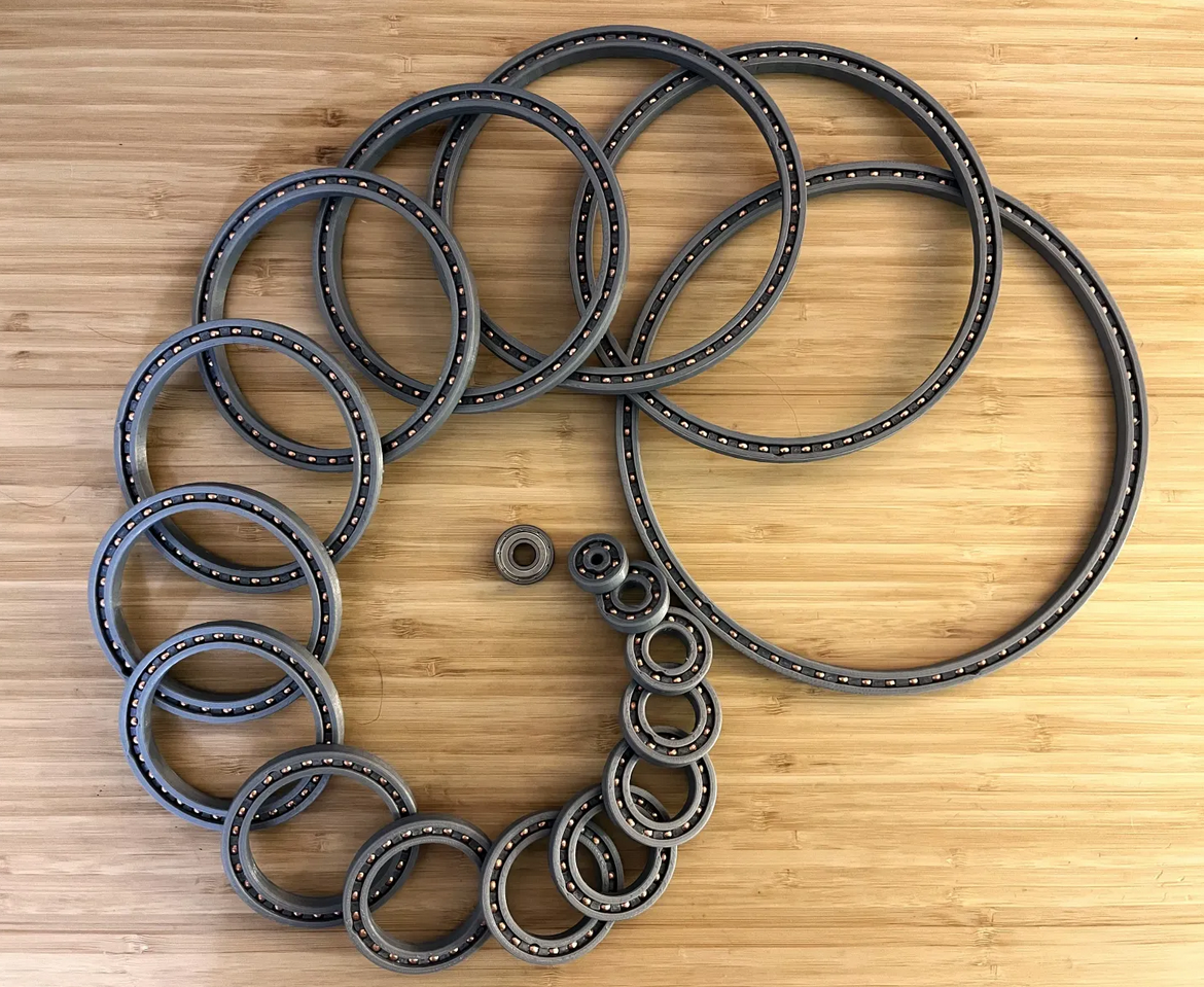
The issue I encountered with the bearing was resolved by removing the spacers. However, while troubleshooting, I discovered a better method for making 3D-printed bearings. This method is outlined in a guide by Dangineering on Printables. He uses BB gun ammo as the balls for his bearing, which is a fantastic idea because they are small and highly precise—something that’s difficult to achieve with 3D printing. Plus, you can get 1,500 of them for around €14. In future designs, I will incorporate this type of bearing.
To address the issue of excessive load on the 180-degree servo, one solution could be to implement a 2:1 gearing ratio between the servo and the rotating part. This would require switching to a 360-degree servo, so that a full 360-degree movement of the servo results in 180 degrees of actual rotation. This approach would reduce the load on the motor.
Build Guide
Since the goal is for the design to be open-source, I created a step-by-step assembly guide.
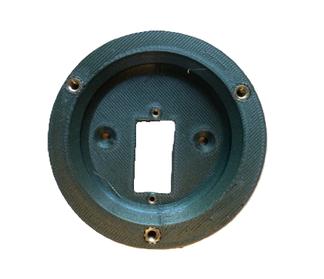
Step 1 & 2
Insert heat inserts:
- M3*OD4.6*H5.7 x3
- M2*OD3.6*H3.6 x2
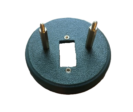
Step 3
Install the spacers using M3 screws:
- Spacer GN 6220-ST-M3-20-B x2
- Hex Flat Countersunk Screw M3x8 x2
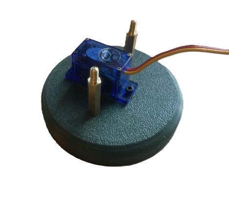
Step 4
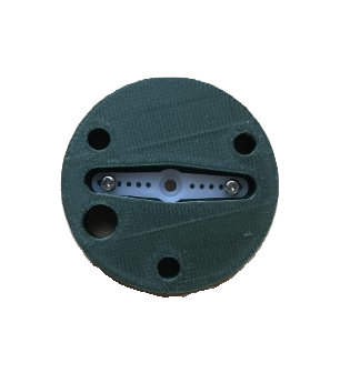
Install the servo using M2 screws with washers:
- Hex Cap Head Screw M2x8 x2
- M2 Washer x2
- TS90M Mini Servo - 1.8kg
Step 5
Install the plastic arm (though screwing it down isn’t necessary).
Step 6
Insert heat inserts:
- M3*OD4.6*H5.7 x3
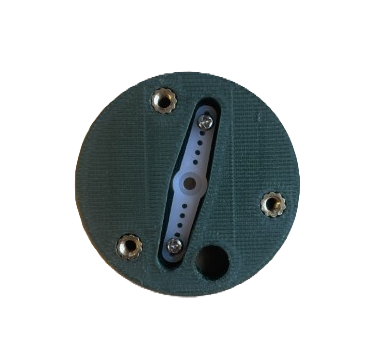
Step 7
Install one plastic part into the other.
Step 8
Since the servo is a 180-degree servo, ensure both M3 screws are accessible through the hole in the middle part.
Step 9
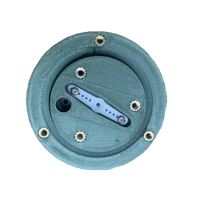
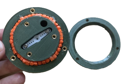
Insert all the small cylinders and grease them. Figure 9 still shows the spacers, but I removed them afterward. I’ll discuss improving the bearing in the recommendationss.
Step 10
Screw the lid onto the bearing using M3 screws. Also, attach the plastic part using the included screw:
- Hex Flat Countersunk Screw M3x8 x3
Step 11 & 12
Insert heat inserts:
- M3*OD4.6*H5.7 x4
- M2*OD3.6*H3.6 x2
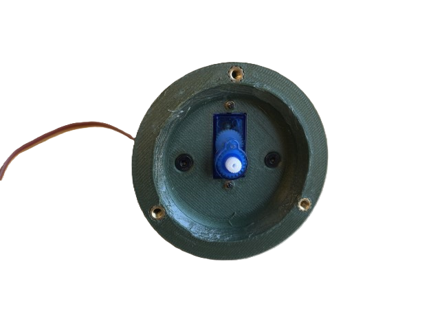
Step 13
Install the servo using M2 screws and washers:
- Hex Cap Head Screw M2x8 x2
- M2 Washer x2
- TS90M Mini Servo - 1.8kg - Continuous
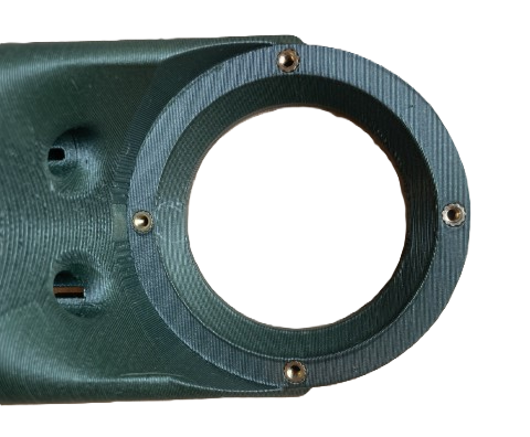
Step 14
Assemble the two parts using M3 screws:
- Hex Flat Countersunk Screw M3x16 x3
Step 15
Insert heat inserts:
- M3*OD4.6*H5.7 x4
Step 16
Insert all small cylinders and ensure they are greased. Figure 16 still shows the spacers, but I removed them afterward. I’ll discuss improvements to the bearing in the recommendations. Afterward, attach the lid using M3 screws:
- Hex Flat Countersunk Screw M3x8 x4
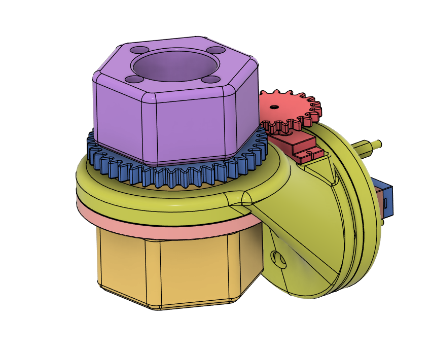
Step 17
Install the large gear on top of what you see in Figure 15. Then place the orange part on top of that and secure it with M3 screws:
- Hex Flat Countersunk Screw M3x20 x4
To install the small gear, use the screw included with the servo.